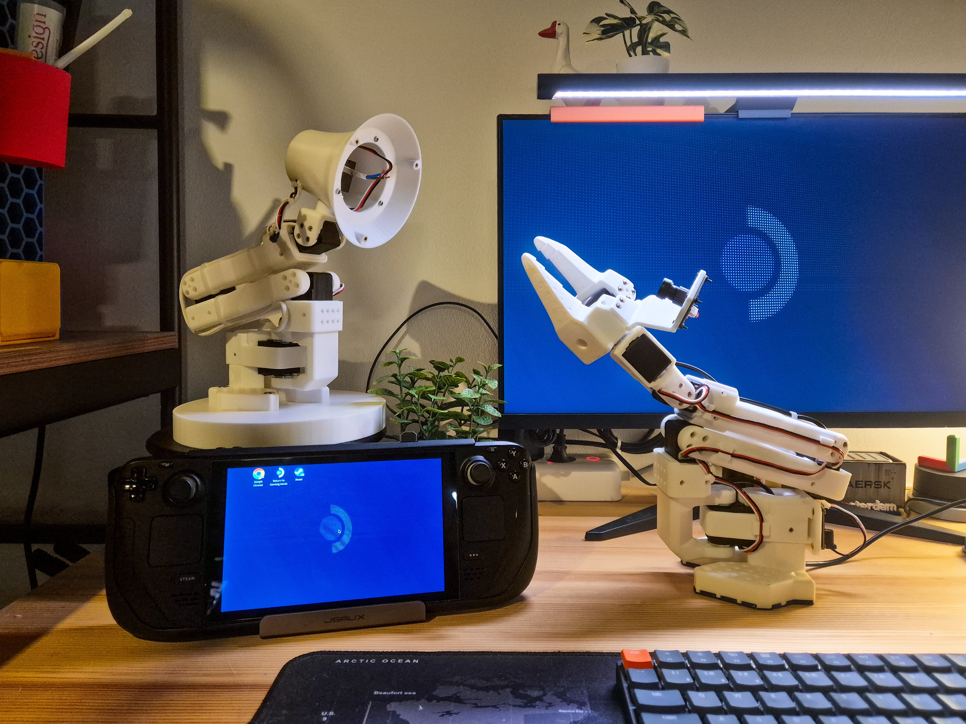

Wiring up ROS 2 Control for LeKiwi
URDF, controllers, and velocity limits for the LeKiwi omni-wheeled base
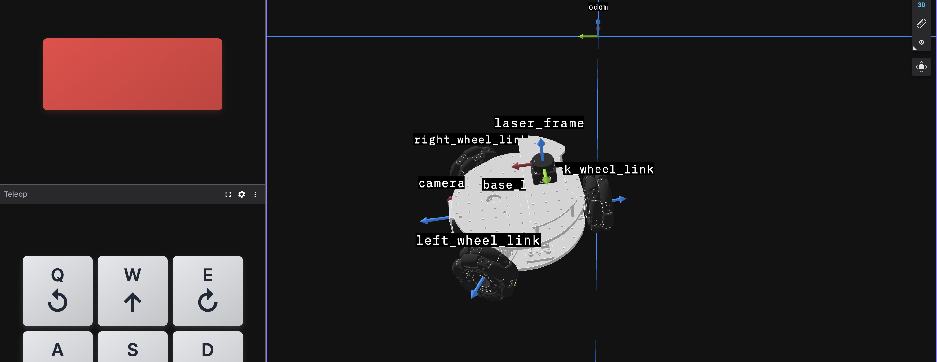
Last month, I built sts_hardware_interface, the ros2_control plugin for Feetech's STS servo motors. That post primarily focused on the hardware abstraction. This one is about connecting it to actual ROS 2 controllers and getting the robot to move the way I want it to. In this post, I focus on three things: the <ros2_control> block in the URDF, the controller config in lekiwi_control, and the fine-tuning (including a rotation issue during strafing that took longer to fix than I'd like to admit).
Setting up ros2_control in the URDF
If you've worked with ros2_control before, the first step is always to set up the URDF. I can write an entire post about it, but to keep this post short, I will direct you to the ros2_control workshop from ROSCon 2022. This is a perfect primer to get started with ros2_control, and personally, a great reference guide that I keep coming back to.
The URDF block
The <ros2_control> block in the URDF tells the controller manager which hardware plugin to load and what interfaces each joint exposes. The controller manager is the central node of the ros2_control framework, and manages the lifecycle of the controllers and handles access to the hardware interfaces.
<ros2_control name="lekiwi_base" type="system">
  <hardware>
    <plugin>sts_hardware_interface/STSHardwareInterface</plugin>
    <param name="serial_port">$(arg serial_port)</param>
    <param name="baud_rate">${baud_rate}</param>
    <param name="use_sync_write">${use_sync_write}</param>
    <param name="enable_mock_mode">$(arg use_mock)</param>
    <param name="max_velocity_steps">${sts_max_velocity_steps}</param>
    <param name="proportional_acc_max">${proportional_acc_max}</param>
    <param name="proportional_acc_deadband">${proportional_acc_deadband}</param>
  </hardware>
  <!-- Left wheel joint (Motor ID 7) -->
  <joint name="left_wheel_joint">
    <param name="motor_id">${left_motor_id}</param>
    <param name="operating_mode">${operating_mode}</param>
    <command_interface name="velocity"/>
    <command_interface name="acceleration"/>
    <state_interface name="position"/>
    <state_interface name="velocity"/>
    <state_interface name="effort"/>
    <state_interface name="voltage"/>
    <state_interface name="temperature"/>
    <state_interface name="current"/>
    <state_interface name="is_moving"/>
  </joint>
  <!-- back_wheel_joint (Motor ID 8) and right_wheel_joint (Motor ID 9) follow the same pattern -->
</ros2_control>
Let's talk about the parameters.
baud_rate,xxx_motor_id, andoperating_modeare self-explanatory.use_mockenables the controller in mock mode, which has been explained in detail in thests_hardware_interfacepost.use_sync_writebatches all three velocity targets into a single packet instead of three sequential commands. This results in lower latency, and all wheels get their updated targets at the same time.sts_max_velocity_stepsis the maximum rated velocity of the motor in steps. I am using STS3215, but other STS series motors have different speed ratings.We will come to the
proportional_acc_maxandproportional_acc_deadbandparameters in a bit.
None of these parameter values are hardcoded. They're all xacro:property definitions in base.control.xacro (in lekiwi_description), so the main URDF stays readable, and all the tunable numbers are in one place.
<xacro:property name="serial_port" default="/dev/ttySERVO"/>
<xacro:property name="baud_rate" default="1000000"/>
<xacro:property name="use_mock" default="false"/>
<xacro:property name="use_sync_write" default="true"/>
<xacro:property name="sts_max_velocity_steps" value="3400"/>

<xacro:property name="proportional_acc_max" value="25"/>
<xacro:property name="proportional_acc_deadband" value="0.05"/>

<xacro:property name="left_motor_id" value="7"/>
<xacro:property name="back_motor_id" value="8"/>
<xacro:property name="right_motor_id" value="9"/>
<xacro:property name="operating_mode" value="1"/>
Note that there are two velocity limits. sts_max_velocity_steps = 3400 is the STS3215 hardware maximum, used as a hard clamp on every write. max_velocity_steps is the self-defined working limit, set to 85% of the rated maximum, for two main reasons:
First, I don't trust the unbranded LiPo that came with the LeKiwi kit (no datasheet, the QR code goes to an app store). So, best to limit the current draw.
At full speed, the motors start missing their velocity targets, which causes odometry to drift. This 85% keeps them tracking.
From max_velocity_steps, the joint limits and other values in control.yaml (in lekiwi_control) cascade automatically; change one value and everything updates.
<xacro:property name="max_velocity_steps" value="${int(sts_max_velocity_steps * 0.85)}"/>
<xacro:property name="max_velocity_rads" value="${max_velocity_steps*2*pi/4096}"/>

<!-- Maximum allowable linear velocity per axis -->
<xacro:property name="max_linear_velocity_x" value="${wheel_radius * max_velocity_rads / (sqrt(3)/2)}"/>
<xacro:property name="max_linear_velocity_y" value="${wheel_radius * max_velocity_rads / 1.0}"/>
<xacro:property name="max_angular_velocity_z" value="${wheel_radius * max_velocity_rads / wheel_base_offset}"/>
Finally, each wheel joint, after declaring its motor ID and operating mode, declares which interfaces it exposes. The hardware interface reads back position, velocity, effort, voltage, temperature, current, and is_moving as state interfaces every cycle. All is defined in the hardware interface; no extra custom code needed.
Configuring the Controllers
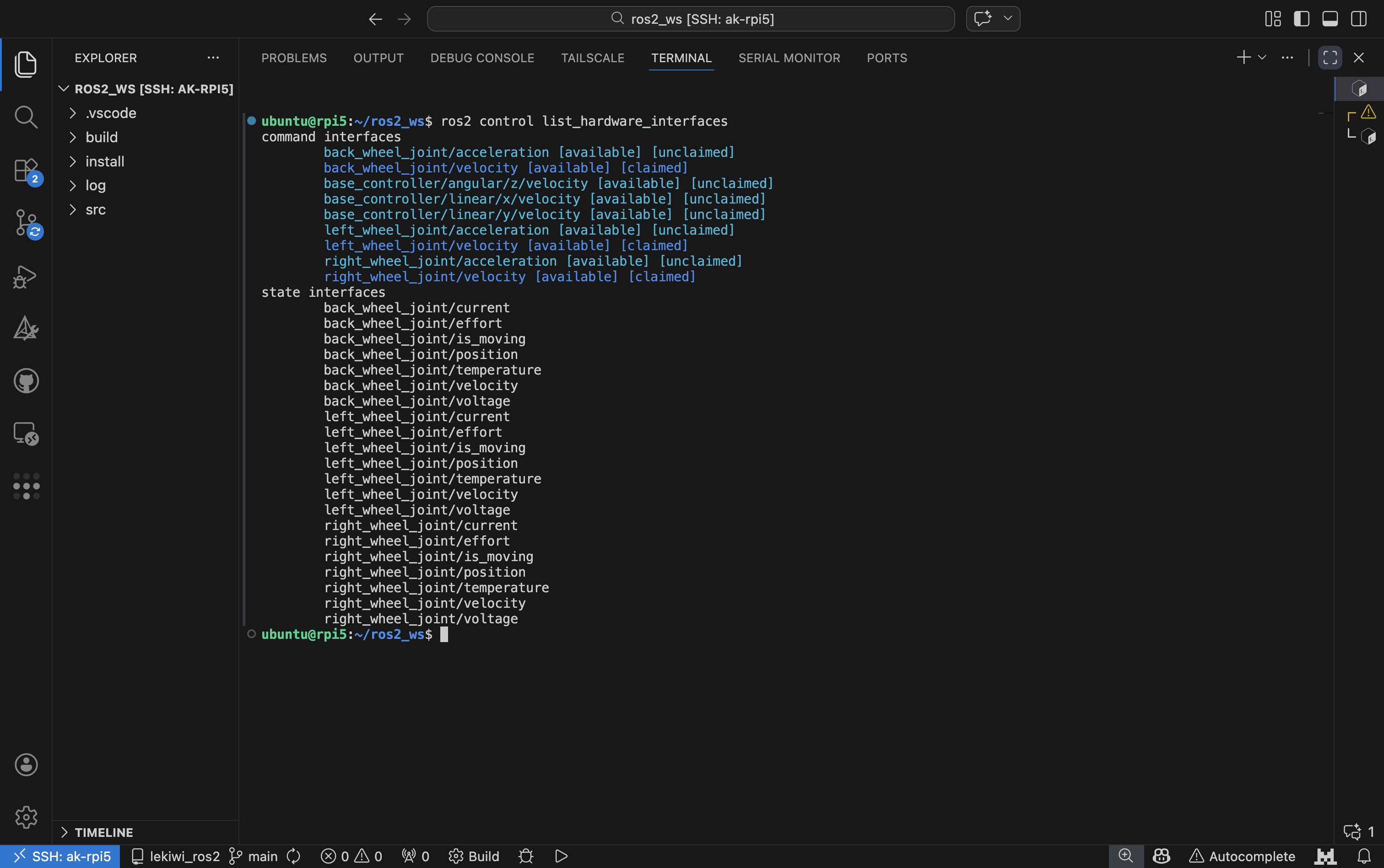
The control configuration is defined in lekiwi_control , which is mostly YAML and launch files, no code. And the configuration is quite simple: just two controllers, running at 50 Hz.
controller_manager:
  ros__parameters:
    update_rate: 50 # Hz
    statistics_publish_rate: 0.0  # Disable /controller_manager/statistics/* topics

    # Command and error handling
    enforce_command_limits: true  # Enforce URDF joint limits via JointSaturationLimiter
    handle_exceptions: true       # Graceful error handling

    # Hardware component initialization
    defaults:
      switch_controller:
        strictness: strict
      allow_controller_activation_with_inactive_hardware: false
      deactivate_controllers_on_hardware_self_deactivate: true

    joint_state_broadcaster:
      type: joint_state_broadcaster/JointStateBroadcaster

    base_controller:
      type: omni_wheel_drive_controller/OmniWheelDriveController

joint_state_broadcaster:
  # joint state broadcaster parameters...

base_controller:
  # omni wheel drive controller parameters...
Key takeaways:
enforce_command_limits: truetells the controller manager to runros2_control'sJointSaturationLimiter, which clamps commands to the URDF velocity limits before they reach the hardware.JointStateBroadcasterpublishes all state interfaces to/joint_statesand/dynamic_joint_states. Temperatures, currents, voltages, stall flags: all of it is accessible using standard ROS 2 tools.motor_diagnostics_nodesubscribes to/dynamic_joint_statesand fires warnings when things go out of range, but that's a separate post for another time.OmniWheelDriveControllerhandles the omni-wheel kinematics using the robot's geometry as parameters. By settingopen_loop: false, the controller measures wheel velocities for odometry rather than commanded targets.
https://www.youtube.com/watch?v=cCn6vuQvdrg
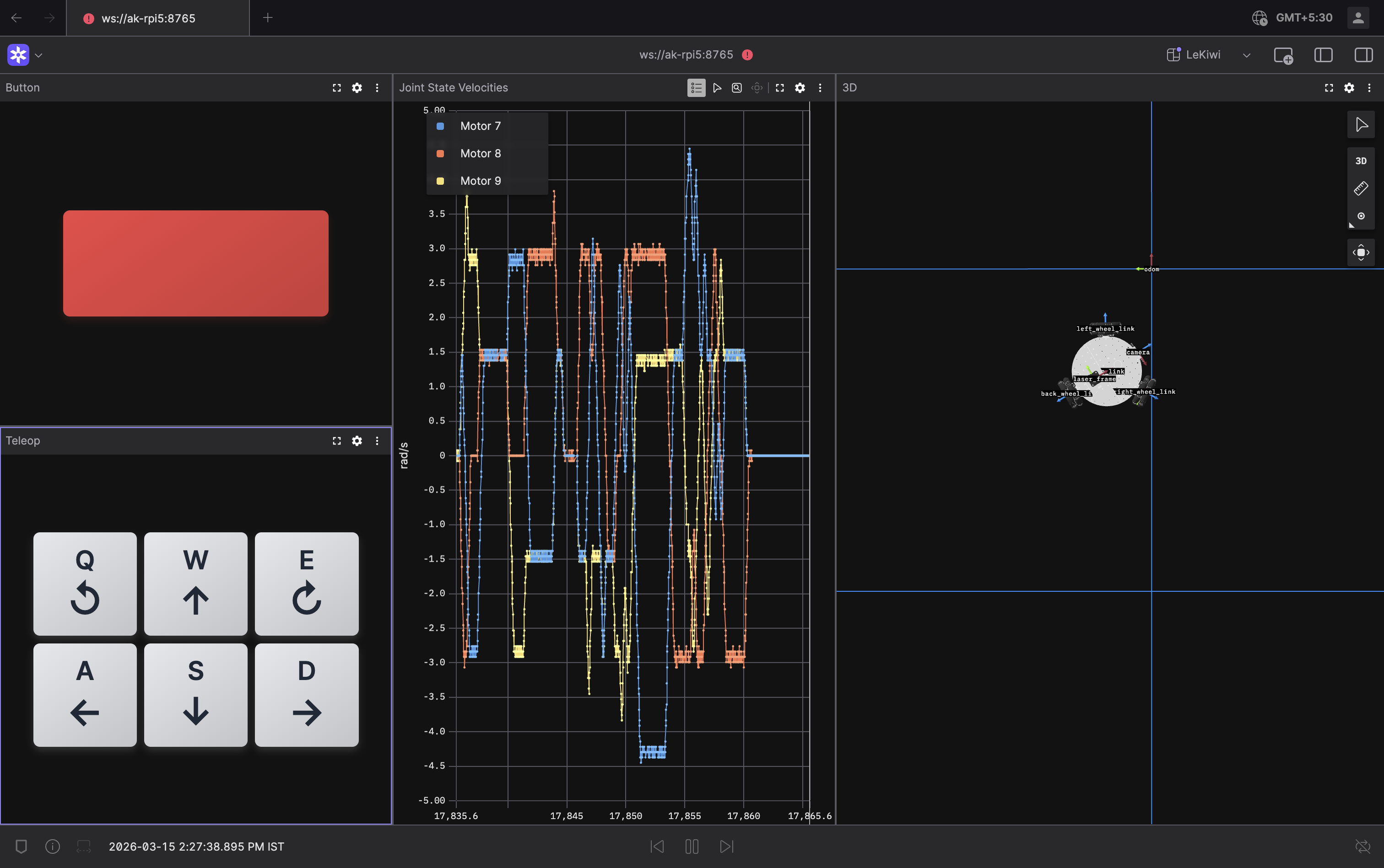
In this video, you can see the robot being driven around as the dynamic joint state topic values update in real time.
Teleoperation
A single teleop_twist_joy node converts incoming joystick inputs (from the joy package) to velocity commands and publishes to /base_controller/cmd_vel.
One thing worth flagging: the parameter publish_stamped_twist must be set to true. The OmniWheelDriveController subscribes to TwistStamped, not plain Twist. Publish bare Twist, and the robot does nothing, which is annoying to debug.
UPDATE: I switched from teleop_twist_joy to joy_teleop instead. joy_teleop allows me to call ROS 2 services as well, which allowed me to configure buttons for enabling and disabling the emergency stop. The normal teleoperation works identically to teleop_twist_joy. I have also reused the same config file for this switch.
The configuration is defined in the teleop.yaml file in lekiwi_control.
https://www.youtube.com/watch?v=wDOlI_AGhKk
Do note that I'm not using this teleop method at the moment. Since I'm working remotely on my robot, I'm using a vibe-coded teleop extension on Foxglove instead. It still has some issues, and once I fix them, I'll write a separate post about it.
Fine-Tuning
Fine-tuning the control system took a few sessions and unearthed some issues. Let me start with the biggest problem first.
The Rotation Problem
This was a confusing one. Every time I tried to move the robot linearly in the Y direction (strafing), the robot rotated a little bit. Let go of the strafe button, and the robot twitched back.
Turns out the cause of this is the three-wheel geometry. For a purely sideways strafe, each wheel gets a different target velocity.
ω_back  = +vy / r         (full change, back wheel at 180°)
ω_left  = −vy / (2r)      (half change, 60° projection)
ω_right = −vy / (2r)      (half change, 300° projection)
This means that the back wheel has to reach twice the speed of the front two. Assuming we are starting from zero, the back wheel has twice the velocity delta to cover. At the time, the ACC register of the motors was set to 0 in sts_hardware_interface. This does not mean zero acceleration; this means zero ramp - all motors just chase their targets as fast as they physically can. So, by the time the front wheels have reached their targets, the back wheel is still catching up, so the speed ratios are all wrong and the chassis rotates. Same thing on deceleration, in reverse.
Synchronised motor ramps
The most straightforward fix is to use the motor's ACC register differently. Instead of sending the same ACC = 0 to all three wheels, sts_hardware_interface now sets it proportionally: the wheel with the biggest speed change gets the highest ACC, the others get lower values. Since ramp time ≈ Δv / ACC, this guarantees equal ramp durations: if one wheel's Δv is twice another's, its ACC is twice as high, so both finish in the same time. All three arrive together:
// From sts_hardware_interface write() — SyncWriteSpe path
double max_delta_rad_s = 0.0;
for (size_t j = 0; j < velocity_motor_indices_.size(); ++j) {
    size_t idx = velocity_motor_indices_[j];
    double target = conversions::apply_limit(hw_cmd_velocity_[idx], ...);
    velocity_sync_velocities_[j] = conversions::rad_s_to_raw_velocity(target, max_velocity_steps_);
    velocity_sync_deltas_[j] = std::abs(target - hw_state_velocity_[idx]);
    max_delta_rad_s = std::max(max_delta_rad_s, velocity_sync_deltas_[j]);
}
for (size_t j = 0; j < velocity_motor_indices_.size(); ++j) {
    if (max_delta_rad_s < proportional_acc_deadband_rad_s_) {
        velocity_sync_accelerations_[j] = 0;  // tiny step — glide to target
    } else {
        int acc = static_cast<int>(
            std::round((velocity_sync_deltas_[j] / max_delta_rad_s) * proportional_acc_max_));
        velocity_sync_accelerations_[j] = static_cast<u8>(std::clamp(acc, 1, STS_MAX_ACCELERATION));
    }
}
servo_->SyncWriteSpe(ids, n, velocities, accelerations);
Two parameters in base.control.xacro tune this:
proportional_acc_max: This is the acceleration set for the motor with the highest delta velocity. The other motors will getACCvalues that are proportional to this. The range is [0, 254]proportional_acc_deadband: This value defines a deadband, which stops the ramp from firing on tiny corrections. If a wheel delta is within this tolerance value, thenACC=0.
Even after this change, the rotation issue doesn't disappear completely; that's a geometry property you can't tune away. But with this fix, and the lower velocity/acceleration limits (covered next), the rotation is minimized significantly.
Velocity Limits
There are three layers of velocity limits, each serving a different purpose:
Hardware ceiling (
sts_max_velocity_steps = 3400): absolute motor maximum, straight from the motor's datasheet. The motor cannot physically go past this limit.Operating limit (
max_velocity_steps = sts_max_velocity_steps * 0.85): 85% of the physical ceiling, allowing for some headroom, and cascades intobase_controllers.yaml.Controller limits (defined in
base_controllers.yaml): deliberately lower than the joint operating limits, and the reason will become clear in a bit.
When I originally calculated the joint limits in SI units based on the operating limit in steps, I did it one axis at a time. But in real life, a mobile robot, especially a holonomic one like the LeKiwi, rarely moves one axis at a time. It is usually a combination of axes in motion at any one time. My original calculation was 0.226 m/s for linear Y and 1.71 rad/s for yaw. But at max strafe + max rotation, the back wheel needs:
ω_back = (vy + R × ωz) / r = (0.226 + 0.132239 × 1.71) / 0.051 = 8.86 rad/s - 2× the joint limit
When enforce_command_limits clips one wheel but not the others, the speed ratios break, and once again, the robot rotates. Same symptom as before, different cause. The fix is to set the controller limits low enough that any multi-axis combination stays within the joint limit
That means lower single-axis ceilings: lateral speed drops from 0.226 m/s -> 0.13 m/s, rotation from 1.71 rad/s -> 0.44 rad/s. The teleop scales match exactly, so full joystick deflection reaches the limit (~4.43 m/s) without breaking it.
Per-Wheel Acceleration
There are two separate acceleration controls, and it's worth being clear about which does what.
The hardware ACC is handled by the proportional scheme explained above. The controller leaves the acceleration interface at zero and sts_hardware_interface updates it every cycle based on each wheel's velocity delta. A big step means high ACC on the back wheel and lower on the front two; a small nudge might not even clear the deadband, and the motors just glide with ACC = 0.
The max acceleration in base_controllers.yaml is a different thing altogether. It limits how fast the speed target is allowed to change, before wheel speeds are even calculated:
linear:
  x:
    max_velocity: 0.13
    max_acceleration: 0.65   # m/s²  — ~200 ms ramp to full speed
  y:
    max_velocity: 0.11
    max_acceleration: 0.55   # m/s²  — ~200 ms ramp to full speed
angular:
  z:
    max_velocity: 0.44
    max_acceleration: 2.2   # rad/s² — ~200 ms ramp to full speed
At 50 Hz, 0.55 m/s² gives a per-cycle step of 0.011 m/s (0.216 rad/s at the back wheel), well above the 0.05 rad/s deadband. That matters: set max_acceleration too low and the per-cycle step falls below the threshold, ACC stays at zero, and the back wheel races to its target unchecked. And now you're back to the rotation problem.
I know this sounds quite confusing; it took me nearly a day to wrap my head around what's happening. But once I set the new velocity and acceleration values, a lot of my issues were resolved, as you can see in the video. Yes, the robot is significantly slower, but there are no surprises in its motion anymore, and no "out of limits" errors.
What's Next?
Next up is integrating my SO-100/101 arm with the LeKiwi base: position-mode arm joints and a PWM/effort-controlled gripper alongside the velocity-mode wheels. That's the mixed-mode case sts_hardware_interface was designed for, and a good real-life stress test for my implementation.
In parallel, I also want to get into autonomy for the mobile base; the sensor hardware (LiDAR and Camera) and ROS 2 driver stack are ready.
If you want to poke around with the packages mentioned in this article, here are the GitHub links:
SCServo_Linux: the C++ SDK for controlling Feetech motors. I didn't mention it explicitely, but it is very important forsts_hardware_interfacests_hardware_interface: the hardware interface implementationlekiwi_ros2: top-level directory that contains the following packageslekiwi_bringup: bringup package with configs and launch fileslekiwi_control: control-related package with configs, nodes, and launch fileslekiwi_description: URDF and meshes for LeKiwi
As always, feedback is welcome, PRs/contributions are really appreciated. More LeKiwi stuff (and a cool Agentic AI project) coming soon...