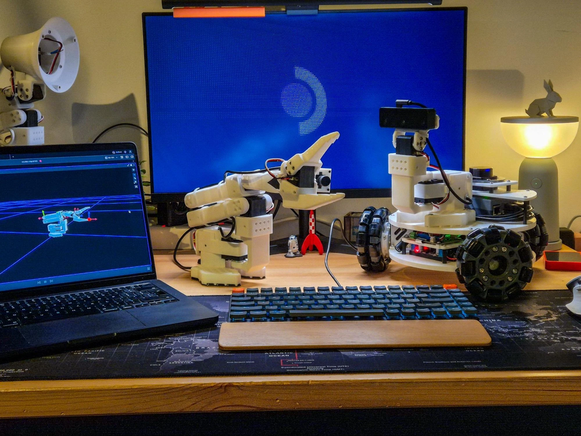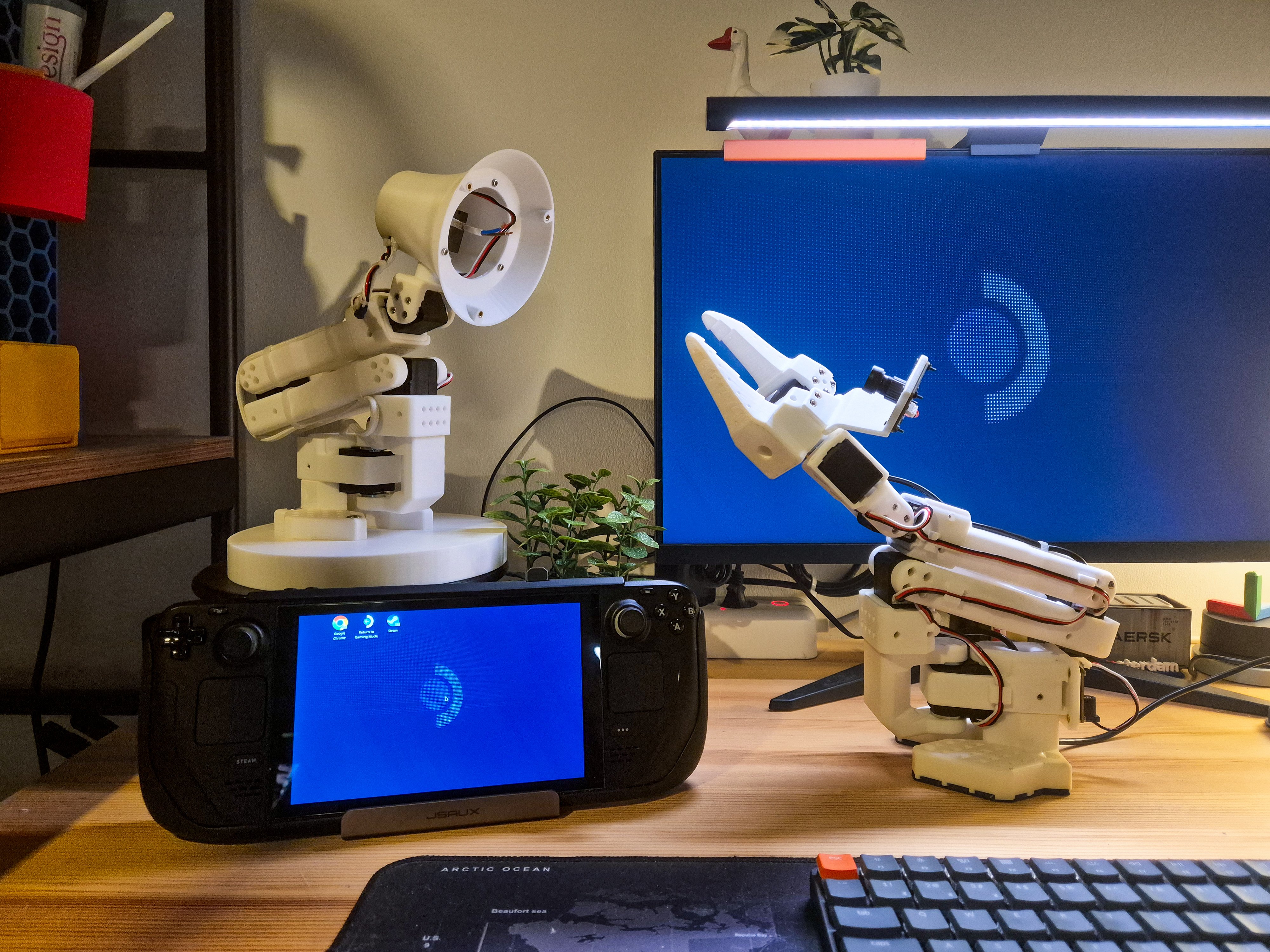

BNO055 IMU Hardware Abstraction
Vibe-coding a ROS 2 Control Sensor (Hardware) Interface for LeKiwi

One of the things I had planned for my ongoing LeKiwi build was adding an IMU. The wheel odometry is already quite accurate, but the more sensors, the better. Especially if it is as good as the BNO055 IMU from Bosch. I genuinely haven't used an easier IMU to work with - it self-calibrates, does sensor fusion onboard, and produces clean results with minimal noise - definitely a must-have for any roboticist's toolkit.
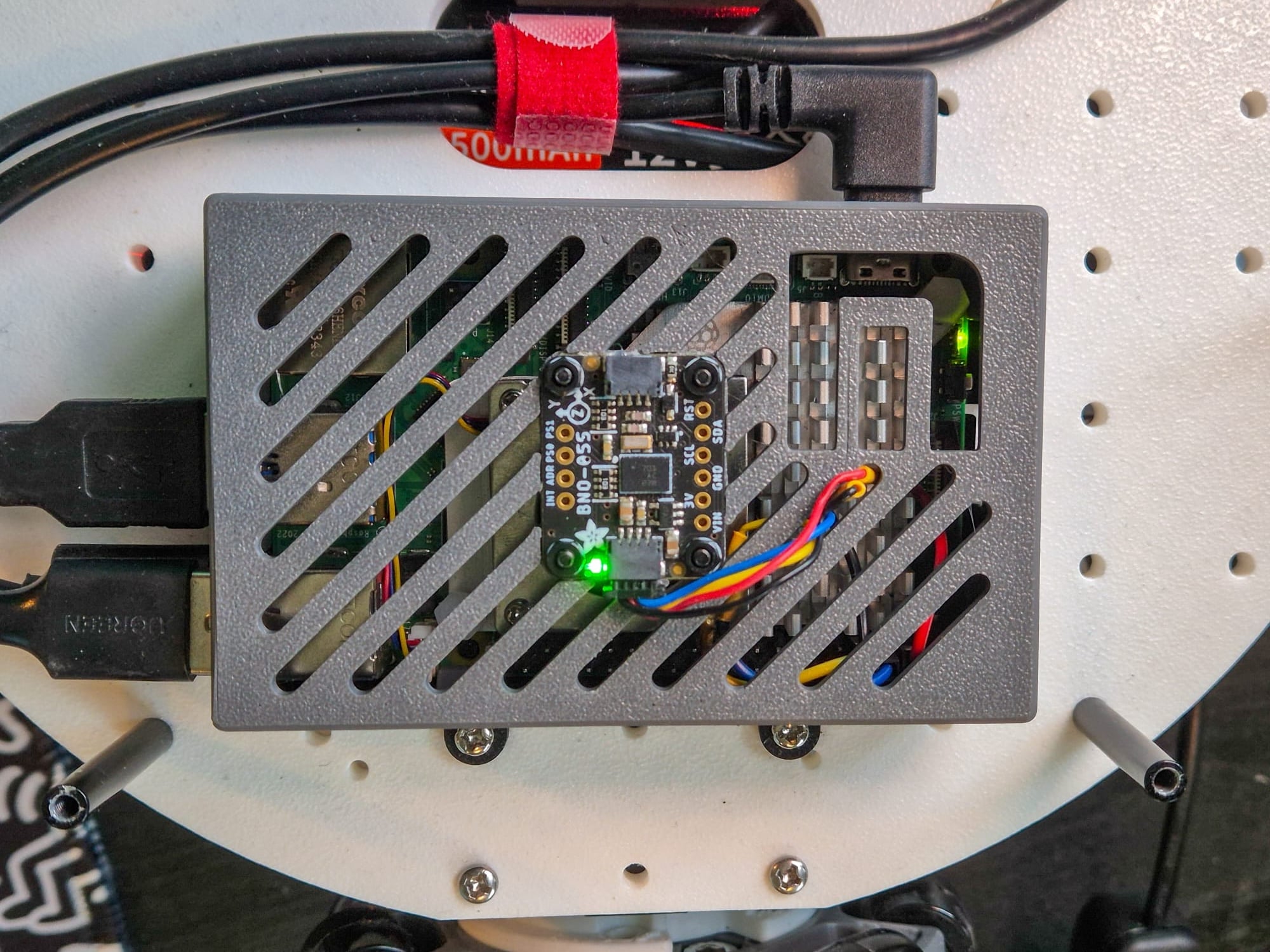
I've used this sensor before, and I normally use it with the bno055 ROS 2 (Python) package, but I had recently learned about the SensorInterface and the imu_sensor_broadcaster controller in ros2_control while developing the sts_hardware_interface package, and wanted to try it out. But I got busy with another project, so I decided to give vibe-coding a shot for this one.
The sts_hardware_interface package, although AI-assisted, was meticulously designed, reviewed, and tested manually. With the new bno055_hardware_interface, I just gave Claude (Sonnet 4.6, using a mix of Claude Code and GitHub Copilot) a bunch of references, including sts_hardware_interface, sensor datasheets, and ros2_bno055_sensor, a ROS 2 package I found, which is written in C++. I then asked it to write me a hardware interface using these references, with occasional guidance along the way. I mostly just focused on my other project.
I did use some Claude skills to do this: in-built skills like /simplify, review skills from coderabbit, and planning skills from superpowers to name a few. I didn't touch the code once. I let the AI agents do everything, from checking whether the sensor was detected over I2C, to running the ROS 2 example and executing the AI-generated tests. After a few iterations and brief manual code reviews, I had it working as expected.
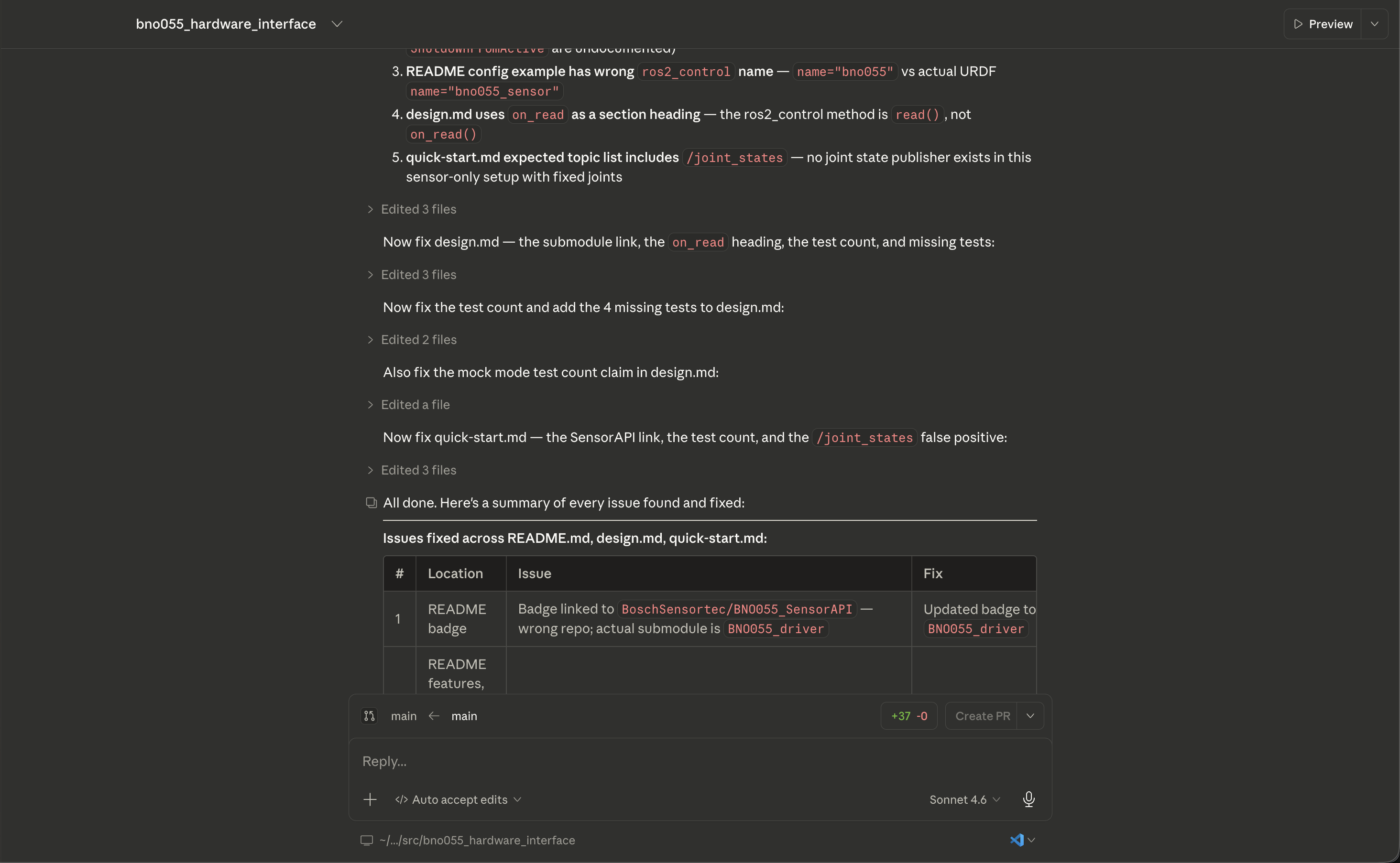
I even asked Claude to write the documentation. I don't mind sloppy code, but I absolutely hate wrong documentation, so I manually verified that the docs matched the implementation.
How it works
The bno055_hardware_interface is a ros2_control SensorInterface plugin that connects ROS 2 to the BNO055 over I2C. Instead of a standalone node that publishes IMU data directly, it plugs into the ros2_control ecosystem — orientation, angular velocity, and linear acceleration are exposed as typed state interfaces consumed by the imu_sensor_broadcaster. Same idea as the sts_hardware_interface, except that one is a SystemInterface (reads and commands actuators) while this one is a SensorInterface (read-only).
The BNO055 runs sensor fusion on-chip, so the host just reads already-fused values. While the sensor supports multiple modes, I limited the hardware interface to three fusion modes, selectable via the sensor_mode launch parameter: NDOF (9-DOF absolute, default), NDOF_FMC_OFF (9-DOF without fast magnetometer calibration), and IMUPLUS (6-DOF, no magnetometer). The IMU normally self-calibrates, but the package also supports calibration persistence: save self-calibrated offsets to a YAML file and reload them at boot.
Most of the work happens in bno055_hardware_interface.cpp, which implements the SensorInterface lifecycle and exposes state interfaces for orientation, angular velocity, and linear acceleration. on_configure handles I2C init, calibration loading, axis remapping, and fusion mode activation. read() updates the state interfaces with scaled sensor data each control loop tick. A mock mode (enable_mock:=true) skips all I2C operations for testing without hardware.
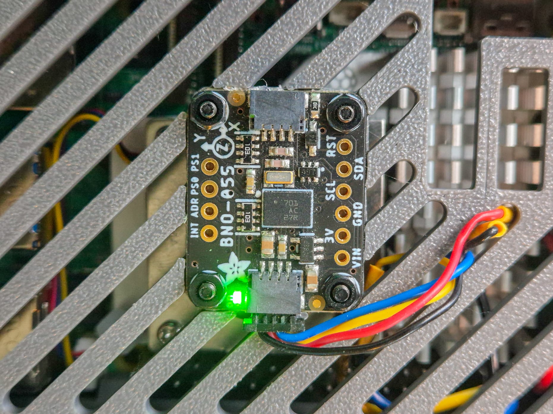
The axis remapping in on_configure is worth mentioning: the BNO055 has 8 predefined placement configurations (P0–P7, per datasheet §3.4) that remap sensor axes to match your mounting orientation, so you don't have to rotate data in software. I used P1, which lines up with the axis labels on the PCB silkscreen.
The plugin uses the official Bosch BNO055 C driver and a thin I2C adapter borrowed from ros2_bno055_sensor. The config/ folder includes a URDF xacro, an imu_sensor_broadcaster configuration, and a template for calibration offsets.

There are also two optional companion nodes. bno055_diagnostics.cpp publishes sensor health (calibration status per sub-sensor, system errors, temperature) to /diagnostics at 1 Hz. imu_tf_broadcaster.cpp republishes IMU orientation as a world → base_link TF transform so that rotations can be visualized in RViz or Foxglove. The video below demonstrates this. However, I don't intend on using this on the LeKiwi since the transform is provided by fusing the IMU data with wheel odometry in the robot's navigation stack (more on this in a future post).
https://youtu.be/MdPBkdxYOkc?si=vfwHCUjZUXJJPjQN
The launch file brings up robot_state_publisher, ros2_control_node, the IMU broadcaster, and the companion nodes (optional; these can be disabled), with hardware parameters exposed as launch arguments.
Wrapping up
After all this, I ended up with a functional, tested package with features I probably wouldn't have bothered implementing myself: mock mode, diagnostics, calibration persistence, and three fusion modes. Would I vibe-code something safety-critical? Probably not. But for a sensor interface on a hobby robot, the trade-off made sense.
The bno055_hardware_interface is available on GitHub. My work on the ROS 2-powered LeKiwi is also online in the lekiwi_ros2 package, expect rapid and sometimes breaking changes as it is in active development. As always, I welcome feedback and contributions.
UPDATE: I was in a meeting at work with some GitHub employees, and I learned about a new term - Spec-Driven Development, or SDD. It turns out that was kind of what I did - get Claude to write a spec for me and then have it implemented. So, I guess this hardware interface is not vibe-coded, then? Either way, please use with caution, especially in safety-critical applications.
About the author
- Generalist engineer, specializing in robotics, embedded systems, and mechatronics.