
Pan-Tilt Controls using ROS 2
Fixing STS Hardware Interface bugs + testing using a new build

In a previous post, I described designing and implementing the sts_hardware_interface — a ros2_control hardware interface for Feetech STS3215 servo motors. The interface supports position, velocity, and effort/PWM control modes, but I had only tested velocity mode, as my main focus was the LeKiwi build. I assumed position mode would work fine, especially for the [0, 2π] range. But a recent issue report on GitHub from @andreasBihlmaier revealed a real problem: negative angles didn't work as expected. As I dug deeper, I found a few more issues.
This post walks through what went wrong, how I tracked down the root cause, the fix, and how I tested it on a new build - a Pan-Tilt mechanism, a two DoF pan-tilt mechanism built from SO-100/101 parts.
The Problem
The STS3215 uses a 12-bit magnetic encoder, giving 4096 discrete steps (0–4095) per revolution. The motor counts clockwise, but ROS 2 follows REP-103, where positive angles are counterclockwise. This means the hardware interface must invert direction when converting between raw steps and radians.
Here’s how the original conversion functions worked:
// Read: motor steps → radians
inline double raw_position_to_radians(int raw_position)
{
  return static_cast<double>(STS_MAX_POSITION - raw_position) * STEPS_TO_RAD;
  // STS_MAX_POSITION = 4095, STEPS_TO_RAD = 2π / 4096
}

// Write: radians → motor steps
inline int radians_to_raw_position(double position_rad)
{
  double normalized = std::fmod(-position_rad, 2.0 * M_PI);
  if (normalized < 0.0) {
    normalized += 2.0 * M_PI;
  }
  int raw = static_cast<int>(normalized * RAD_TO_STEPS);
  return std::clamp(raw, 0, STS_MAX_POSITION);
}
This mapping only works for joints that move in the [0, 2π] range. But when you set joint limits to [-π, π], a few problems appear:
1. Position feedback is always positive
raw_position_to_radians always returns values in [0, 2π] regardless of joint limits, which only clamp outgoing commands. A servo at the center reports π rad instead of 0.
2. Negative commands take the long way around
Let's say you give the command to move -0.1 rad, the servo should move a small amount in the clockwise direction, around 65 encoder steps. Since 0 rad sits at step 4095, the servo travels 4030 steps to get to step 65 — nearly a full revolution in the wrong direction.
3. The read/write round-trip was broken
I also discovered that the two functions weren’t true inverses:
| Operation | Result |
|---|---|
| Write 0 rad | fmod(-0, 2π) → step 0 |
| Read step 0 | (4095 - 0) × STEPS_TO_RAD → 2π rad |
So, writing 0 radians gives step 0, but reading step 0 returns 2π radians. The functions disagree about which end of the encoder is 0.
All three problems share the same root cause.
Root Cause
Two formulas, neither being algebraic inverses of each other:
Read: step 4095 is 0 rad
Write: step 0 is 0 rad
For all positive angles strictly inside (0, 2π), both formulas produce results that look plausible, so the inconsistency is hidden during normal testing. The bug only surfaces at the boundaries and for negative angles.
The Fix: A Configurable Center
To fix this, a single unified formula with a configurable center parameter was implemented, with the center parameter being the encoder step that maps to 0 rad:
constexpr int STS_DEFAULT_CENTER = 4095;

inline double raw_position_to_radians(int raw_position, int center = STS_DEFAULT_CENTER)
{
  return static_cast<double>(center - raw_position) * STEPS_TO_RAD;
}

inline int radians_to_raw_position(double position_rad, int center = STS_DEFAULT_CENTER)
{
  double steps = std::round(static_cast<double>(center) - position_rad * RAD_TO_STEPS);
  return static_cast<int>(std::clamp(steps, 0.0, static_cast<double>(STS_MAX_POSITION)));
}
Values outside the encoder's physical range are now clamped to [0, 4095] rather than wrapped with fmod. This default center=4095 preserves existing behavior, while fixing the bugs.
How to Use It
Set position_center_steps to the encoder step (0–4095) that maps to the center position, or 0 rad for each joint:
<ros2_control name="my_hardware" type="system">
  <hardware>
    <plugin>sts_hardware_interface/STSHardwareInterface</plugin>
    <param name="serial_port">/dev/ttyACM0</param>
    <!-- ... -->
  </hardware>
  <joint name="pan_joint">
    <param name="motor_id">1</param>
    <param name="operating_mode">0</param>
    <param name="position_center_steps">2048</param>
    <!-- ... -->
    <command_interface name="position"/>
    <state_interface name="position"/>
  </joint>
</ros2_control>
Set it to 2048 for a symmetric [-π, +π] range, or 4095 for [0, 2π]. Values outside the [0, 4095] range are rejected at startup. The Pan Tilt 100 uses this exact parameter: 2048 for the pan axis and 2646 for the tilt axis, which is calibrated to that motor's physical resting position.
Note that this only applies in position mode (operating_mode=0), it is ignored with a warning on velocity or PWM mode joints.
What Changes for Existing Users?
Almost nothing, the center position defaults to 4095, matching the old behavior for all non-zero inputs. All other angles are unaffected. To see this working on real hardware, the next section walks through the Pan Tilt 100 build.
Real-World Example: Pan Tilt 100
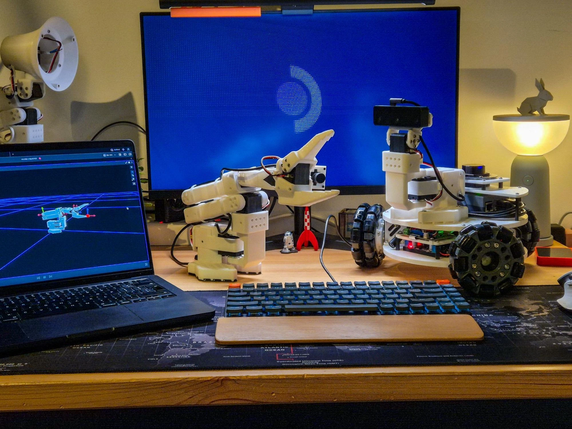
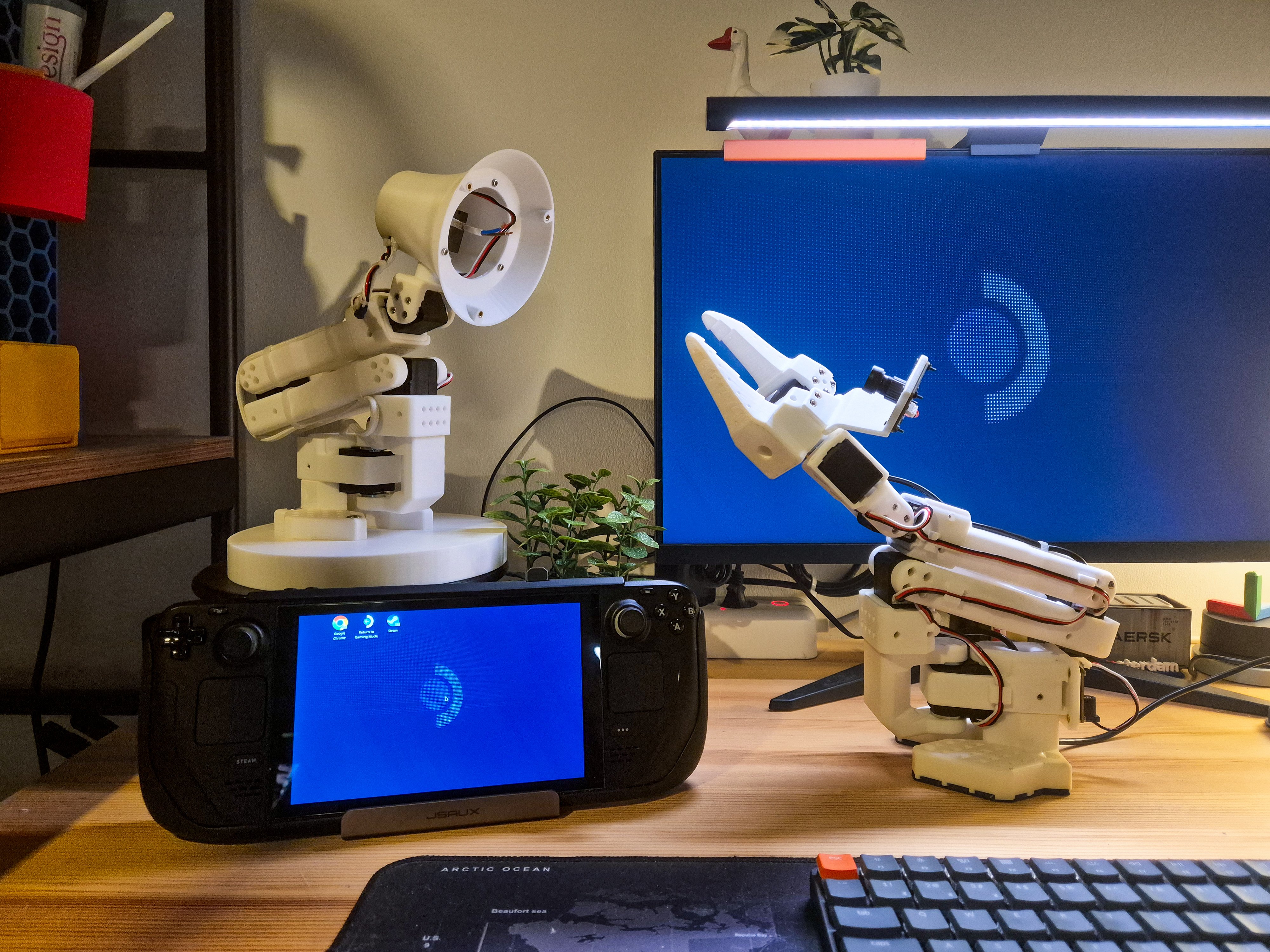
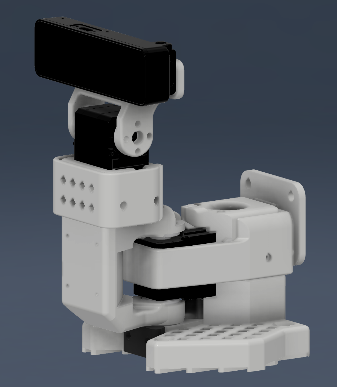
The original plan was to attach a SO100 arm to the LeKiwi. I had some spare motors, so I decided to assemble an arm, and I started printing fresh parts in white PLA. Unfortunately, I ran out of filament halfway through. While waiting for more filament to arrive, it clicked: two motors are all I need to test the hardware interface in position mode, and it also works perfectly as a pan-tilt mechanism. So, I stopped the arm build right there, bolted an OAK-D S2 to the second link with a 3D printed mount, and inspired by the SO100, called it the PT100, where PT stands for Pan Tilt.
The camera integration - VIO, VSLAM, and whatever else follows - is a topic for another post. Getting the depthai-ros wrapper to work was its own adventure nightmare.
URDF and hardware configuration
The PT100 has two joints — pan_joint and tilt_joint, both running in position mode through sts_hardware_interface. The relevant part of the control xacro:
<ros2_control name="pt100_control" type="system">
  <hardware>
    <plugin>sts_hardware_interface/STSHardwareInterface</plugin>
    <param name="serial_port">/dev/ttySERVO</param>
    <param name="use_sync_write">true</param>
    <param name="max_velocity_steps">3400</param>
  </hardware>

  <joint name="pan_joint">
    <param name="motor_id">1</param>
    <param name="operating_mode">0</param>
    <param name="min_position">-1.5708</param>
    <param name="max_position">1.5708</param>
    <param name="max_velocity">4.43</param>
    <param name="position_center_steps">2048</param>
    <command_interface name="position"/>
    <state_interface name="position"/>
    <!-- velocity, effort, voltage, temperature, current, is_moving -->
  </joint>

  <joint name="tilt_joint">
    <param name="motor_id">2</param>
    <param name="operating_mode">0</param>
    <param name="min_position">-1.5708</param>
    <param name="max_position">1.5708</param>
    <param name="max_velocity">4.43</param>
    <param name="position_center_steps">2646</param>
    <command_interface name="position"/>
    <state_interface name="position"/>
    <!-- velocity, effort, voltage, temperature, current, is_moving -->
  </joint>
</ros2_control>
The pan joint was assembled at its original mid-point, and uses position_center_steps: 2048, providing a symmetric [-π/2, +π/2] range. The tilt joint uses position_center_steps: 2646, calibrated to its physical resting position, which isn't at the exact midpoint due to how the link is assembled.
max_velocity is capped at 85% of the hardware max (3400 steps/s → 2890 steps/s ≈ 4.43 rad/s), leaving headroom for the motor to decelerate without overshooting.
The controller is a ForwardCommandController on the position interface, running at 50 Hz. With use_sync_write: true, both joints are commanded in a single serial transaction each cycle.
One non-obvious URDF detail: both joints set velocity="1e6" in their <limit> elements and has_velocity_limits: false in the controller config. joy_teleop sends absolute position targets, so when the joystick moves quickly, the commanded jump can be nearly π rad in a single cycle. ros2_control's JointSaturationLimiter would clamp that to the URDF velocity limit and log spurious "command out of limits" errors every cycle. Setting the limit to a physically unreachable value disables that clamping without touching position enforcement. The sts_hardware_interface still caps actual motor speeds via max_velocity.
For manual control, I use the Steam Deck's gamepad with joy and joy_teleop: left stick for pan/tilt (±π/2 rad at full deflection), L1 as a deadman switch. The A and B buttons call the /emergency_stop service — provided by sts_hardware_interface to enable or disable a hard stop independently of the deadman switch.
https://www.youtube.com/watch?v=avtmbQLGMdY
The fix in action
The results, including plots showing joint command tracking is shown in the video below, visualized on Foxglove. For some time, you also see the input command plot changing, but the joint states don't move; this is because I had pressed the emergency stop at that time.
https://www.youtube.com/watch?v=lExx9SFCsuE
E-Stop and out-of-range positions
During testing, I ran into a second issue, separate from the conversion bug.
When the e-stop is active, torque is disabled, and both joints can be moved freely by hand. If a joint drifts, maybe by gravity, or it is deliberately pushed past its URDF-defined limits while torque is off, ros2_control's JointSaturationLimiter detects the out-of-bounds position the moment the e-stop is released and immediately deactivates the controller. No warning or recovery path, the controller just stops.
The fix: always clamp the position reported by read() to within the URDF limits whenever limits are defined:
if (has_position_limits_[i]) {
  hw_state_position_[i] = std::clamp(hw_state_position_[i], position_min_[i], position_max_[i]);
}
ros2_control now always sees a position within bounds. The write path already clamps commands to the same range, so on the first cycle after e-stop release, the motor is commanded to the nearest limit and moves back into range, while the controller stays active throughout.
Takeaways
If two conversion functions are supposed to be inverses, always test that they actually are. A simple round-trip test (
read(write(x)) ≈ x) would have caught this bug early.Be cautious with
fmodfor angle wrapping in servo code. It can silently map valid negative commands into the wrong part of the encoder range.When hardware can move outside software limits — during e-stop, power loss, or manual handling — clamp the reported state unconditionally before it reaches
ros2_control. Otherwise, this could deactivate the controller, which needs manual intervention to reactivate.By defaulting to backward-compatible behavior (center=4095) and exposing the new parameter, existing deployments like
lekiwi_ros2running in velocity mode or position mode, motors operating in the [0, 2π] range are unaffected.
You can find these changes in sts_hardware_interface. If you use STS3215 servos in position mode and need negative angles, set position_center_steps to your servo’s calibrated center position. The Pan-Tilt implementation can be found in the pantilt_ros2 repository.
Alongside these fixes, the recently merged PR #10 adds a ready-to-use single-motor position mode example, including a URDF, controller config, launch file, and integration tests. You can test the new parameter with use_mock:=true before connecting any hardware.
What’s Next?
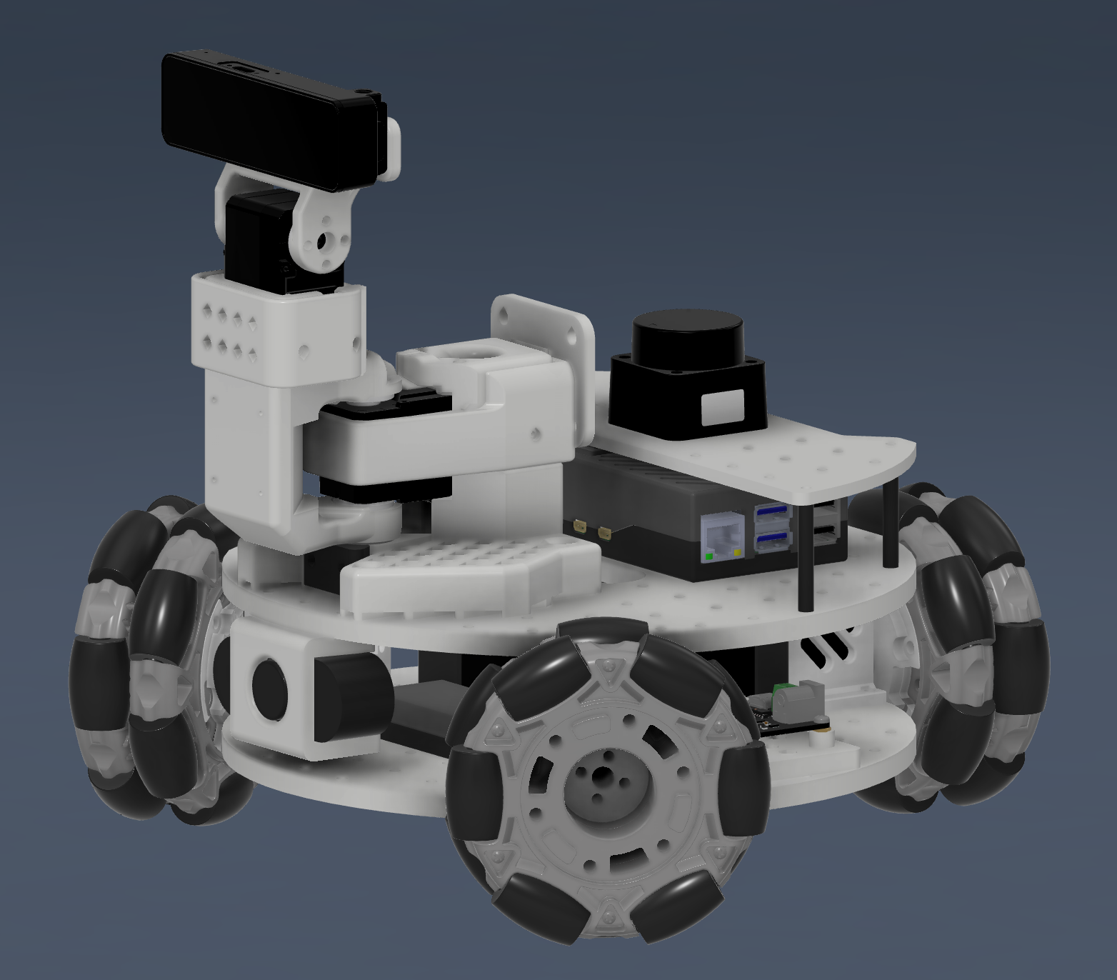
With the hardware interface bug fixed and the Pan Tilt 100 running smoothly in position mode, the next steps are to integrate with lekiwi_ros2. I changed my mind about the SO100 arm; I prefer having a pan-tilt mechanism with an OAK-D S2 depth camera instead. The LeKiwi build is now finally taking shape, moving from a mobile manipulator build to a complete mobile perception platform.
About the author
- Generalist engineer, specializing in robotics, embedded systems, and mechatronics.